Ultrasound
Definition
Ultrasound is cyclic mechanical vibration with a frequency greater than
the upper limit of human hearing, which is approximately 25 kilohertz (25,000
hertz) in healthy, young adults
|
Vibration
and Wave in physics
- A vibration source in
a mechanical medium will cause wave propagation.
- Ultrasound is a
mechanical wave, cannot exist in vacuum.
- Ultrasound transfer
energy within the medium, does not transfer
mass. See a particle
vibration example
- Longitudinal wave:
particle movement in the same direction to the wave propagation. See a one-dimension
example
- compression: Ultrasound
propagation causes local medium density and pressure varying with time.
The density or pressure will increase when it is compressed.
- rarefaction: When low pressure
pass through, the local density will drease.
- Transverse wave:
particle movement in the direction perpendicular to the wave
propagation. See a
one-dimension example
|
Ultrasound
Parameters
- Frequency: The number of times a
vibrating particle goes through its original position within one second.
The unit is “Hertz” or simplified as “Hz”. For
ultrasound, the frequency is around mega hertz, or “MHz”.
- Propagation speed: The distance that the
wave peak pass within one second. It is
determined by elasticity and density property of the acoustic medium.
- Wave length: The distance between
the two adjacent wave peaks
- Amplitude: For vibration, the
amplitude is maximal distance a particle moves away from its original
position.
- Pressure: Wave
propagation can be understood as the
particles vibration abound their balance position, also can be think as
pressure alternatively variation in the acoustic medium. Pressure,
especially from the surface, cause particle to move. Take a small volume
inside the acoustic medium, when more neighbor particles move in, a high
pressure is introduced, and on the contrary, when the particle move out,
a low pressure in generated.
- Power: Since the particles
are vibrating, it possesses kinetic velocity and energy. An ultrasound
source will generate energy, and this energy divided by time is power.
When frequency is fixed, the power is proportional to the density and
second power of particle vibration amplitude. When particles have the
same vibration amplitude, the power will be proportional to the fourth
power of the frequency.
- Intensity:
it is
the power on unit area.
|
Medium
Acoustic Property
- Air: Only low frequency
ultrasound can propagate in air at a speed of 300m/s with a very high
attenuation. The acoustic impedance of air near zeros.
- Water: Sound velocity in water
is around 1500m/s at room temperature. Water has very little attenuation
to ultrasound. The acoustic impedance of water is about 1.5MRayl.
- Soft tissue: Sound velocity in
soft tissue is around 1540m/s. The attenuation of soft tissue is around 0.3 dB/cm/MHz. The acoustic impedance of soft tissue is around
1.5MRayl.
- Bone: Sound velocity in
bone is much fast that in soft tissue. Bone also has a higher
attenuation. Normally, ultrasound beam cannot penetrate bone.
|
Ultrasound
Reflection
- Big surface: The surface
must be big compared to the ultrasound wavelength when reflection
happens.
- Impedance mismatch:
The acoustic impedance on both side of the surface must be different.
- Wavefront pattern: The
reflected wave from a spherical wave emitted from a point has the same
shape as that emitted from its mirrored counterpart.
- Dependence on angle:
For plane wave, the reflected wave has the same angle to the surface as
that of incident wave.
|
- Small
particle size: Ultrasound will be scattered when encounters a small
particle compared to its wavelength.
- Impedance
mismatch: The particle must have a different
acoustic impedance from its background.
- Independence
of angle: The scattered wave will spherical when the particle size is
very small.
|
Ultrasound Refraction
- Big
surface: Ultrasound refraction only happen at
big surface compared to its wavelength.
- Velocity
mismatch: The acoustic medium at both sides of the surface must have
different sound velocity.
- Dependence
on angle: The refracted wave obey Snell's Law.
|
Ultrasound
Attenuation
- Causes of ultrasound
attenuation:
- Scattering
- Absorption
- Reflection
- Ultrasound attenuation
values in type of tissue: Water has minimal attenuation to ultrasound.
Blood has an attenuation of 0.03dB/cm/MHz.
Soft tissue has a value of 0.3dB/cm/MHz. Air,
bone, stone, and metal will normally attenuate all the imaging
ultrasound beam energy they encountered.
- Ultrasound attenuation
values increase with frequency.
- Effects on image: Far
field image will look darker without compensation. Resolution in far
field is lower than near field due to the downshift of the center
frequency of the echo.
|
Ultrasound
Frequency Range and Application
- HIFU: Depends on application,
low than half of the diagnostic frequency.
- Abdominal imaging: 3.5
~ 5 MHz.
- Cardiovascular
imaging: 2.5 ~ 3.5MHz.
- Ophthalmology, eye
application: 15 ~ 50MHz.
- Dermatology, skin
application: 15 ~ 50 MHz.
- Small organ: 5 ~
12MHz.
- Peripheral vascular: 5
~ 10 MHz.
- Intravascular (IVUS):
10 ~ 50 MHz.
- Frequency,
Penetration, and spatial resolution: Higher frequency gives better
resolution, and less penetration. The transmitted power of ultrasound
pulse for imaging is regulated by FDA. The highest energy within FDA
regulation is always used for the best signal to noise ratio. As long as
the signal from the farthest depth has enough SNR, the highest frequency
is always the first choice.
|
Image
Characteristics Related Terminology
- Echogenic: Scatter or
reflect strong echo in general, like bone, stone, or air.
- Anechoic: No echo
area, like water or blood pool.
- Hyperechoic: Generate stronger or
increased echo than surrounding area, like a solid mass in soft tissue.
- Hypoechoic: Opposite to hperechoic, generate weaker or decreased echo than
surrounding area, like a lipid pool or cyst.
- Isoechoic: Generate echo with
normal amplitude, like normal soft tissue.
- Homogeneity:
Parameters like acoustic impedance, geometry texture structure uniform in
the area, such as healthy liver tissue.
- Heterogeneity:
Contrary to homogeneity, contains dissimilar elements, like kidney or
breast.
|
Piezoelectric
Effect
- Piezoelectricity is
the ability of some materials (notably crystals and certain ceramics) to
generate an electric potential in response to applied mechanical stress.
The material that shows piezoelectricity is called piezoelectric
material. Applied electrical charge on both sides of a piece of
piezoelectric material, it will cause stress inside and thus generate
deform. If the electrical charge is alternative, the piece of material
will oscillate and generate mechanical wave. The piezoelectric material
has a special structure that will cause positive and negative charge
center mismatch when an external stress is introduced from certain
direction. Piezoelectric ceramic have many small regions inside it,
called “domain”, and each domain has its own piezoelectric
direction. When an external stress is introduced, some domains give
positive charge if they are lined up according to the stress direction;
some domains may give very minimal charge if its own direction is
perpendicular to the stress direction; and some domains will give
negative charge if it is against the stress direction. The domains are
very small at level of a few microns to hundreds microns, and normally
they are randomly distributed, without special processing to line up all
the domains, the material will not show
piezoelectric as a whole piece. The processing is called poling, use a
high DC voltage applied on both sides of the piece of material for a
short duration of time, such as 1 to 10 seconds. Different material
needs different voltage to reverse the domains, and this voltage is
called coercive voltage. Pure piezoelectric crystal may be a single
domain and doesn’t need poling.
- Curie temperature:
When temperature is high enough, the piezoelectric domains inside
ceramic will have such a high kinetic energy and it will break away from
the poling direction and resume to its original random direction. This
temperature is called Curie temperature. Piezoelectric ceramic will lose
its piezoelectricity when its temperature is above its Curie
temperature.
- Kt: It is thickness
mode mechanical-electrical coupling efficient, the key indicator of
piezoelectricity performance of the material in thickness mode. By
definition, it is the ratio of energy send out to the energy stored by
the material. Without piezoelectricity, a ceramic plate with two sides
coated with electrodes will behave as a capacitor,
the impedance will only have imaginary part, no real part. The current
go through it and the voltage applied on it will be always 90 degree to
each other and thus no energy is emit out but all stored and released.
With piezoelectricity effect, at resonant frequency, the impedance will
have real part and imaginary part, the real part will consume electrical
energy, convert it into acoustic.
- Common piezoelectric
materials: commonly used piezoelectric materials are ceramics, crystals
and polymers. Crystal usually has lower Kt, and
it not good for thickness mode, but good in bar mode. Ceramic has a
better Kt, good in thickness mode. Both of
crystal and ceramic have high acoustic impedance, usually above 30Mryls.
Matching layers are required to transmit acoustic
|
Transducer
Construction and Characteristics
- Thickness resonance
mode: The positive and negative charge center will mismatch and form a
dipole when external force is applied. The dipole direction maybe
parallel or perpendicular to the external force direction. For most
ultrasound application, the transducer is a plate of piezoelectric
material with two sides coated with electrodes. With this structure, the
dipole direction will be parallel to the external force, called 3-3 mode
or thickness mode. There are also transducers in the other way, the
stress and electrical field perpendicular, called 1-3 mode, are common
in low frequency application range.
- Bandwidth and Q: When
it says the transducer has a center frequency of 5MHz, it doesn’t
mean the transducer only works at exactly 5.0MHz, and it won’t
work at 5.1MHz or 4.9MHz. It always has a range, and it is called
spectrum if it drawn with vertical axis as magnitude and horizontal axis
as frequency. Most good transducer will have bell or Gaussian shape spectrum
curve. It has best response to the input excitation at center frequency,
and the response will become weak as the excitation frequency moves away
from the center frequency. On the spectrum, with the maximum point
marked as 0dB, two points can be found at both sides with magnitude of
-3dB, -6dB, or any other number you can name. The frequency range
between these two data points is called Bandwidth. It is obvious that
bandwidth is always linked with a dB level, such -3dB bandwidth or -6dB
bandwidth. On the voltage spectrum, -6dB is often used, and on the power
spectrum, -3dB is more commonly used. Q is a simple name of
“Quality factor”, is the ratio of center frequency over the
bandwidth. The lower the Q, the wider the bandwidth,
and the pulse will be short. For ultrasound imaging, the transducer need
transmit a very short pulse to achieve sharp resolution, and thus a low
Q is required for the whole system, or we can say, the imaging system is
a wide band width system.
High Q system is for resonant, for example, a crystal watch has a
very high Q.
- Damping: Damping is to
decrease the system Q. For ultrasound transducer, it normally means the
backing layer. Heavy damping results in wide bandwidth, short pulse
length, but lower sensitivity. Doppler transducer usually has lower
damping, and thus a higher sensitivity can be achieved since the Doppler
signal is normally weak because it is generated from blood scattering.
- Matching layer: Most
medical ultrasound transducer is based on piezoelectric ceramic or crystal,
having a very high acoustic impedance (about 30MRyl), and human acoustic
impedance is only about 1.5MRyls. Without matching layer, the vibration
of the ceramics will be bounce back and forth inside itself and
gradually die out, only a small port of energy
can be released to the tissue with each time of bouncing. The final
pulse enter the tissue will be long with a lower amplitude. With a
proper matching layer, the pulse will enter the tissue with minimal
lengthened.
|
Ultrasound
Beamformation
- Interference
phenomena: Sound is an acoustic wave, following the superposition
principle. Acoustic wave cause pressure at each
location of the medium vary with time, and thus the particles to
vibrate with time. If the pressure or the displacement of the particle
is recorded, in most cases, it is a sinusoidal function: y = A sin
(2π f t + Ф ), A is the amplitude, f is frequency and
Ф is the initial
phase. Inside the acoustic
medium, or the acoustic field, Ф varied with location, and
amplitude and frequency are the same if we don’t consider the wave
spread and attenuation. If two pressure waves propagate to a single
point, the final pressure at the point will be arithmetic summation of
these two: y =
A1 sin (2π f1 t + Ф1 ) + A2 sin
(2π f2 t +
Ф2 ).
Depends on frequency and initial phase, the combination can be
stronger or weak compared to the incident waves, and can even become
zero if the two have the same amplitude and frequency, but opposite
initial phase. If the wave sources and acoustic field are fixed, the
initial phase for each location will be fixed too, and thus vibration at
some points will be enhanced while other points may be weakened
consistently.
- Huygen's principle: This
principle of wave analysis, proposed by the physicist Christiaan Huygens (1629-1695), basically states
that: Every point of a wave front may be considered the source of
secondary wavelets that spread out in all directions with a speed equal
to the speed of propagation of the waves.
- Aperture size and
wavelength: The aperture is the active area that transmits or receives
acoustic wave at certain moment. For a single-element transducer, the
aperture size is the transducer element size. For array transducer, the aperture are all the elements that works together
simultaneously. To achieve a confined beam, the aperture size need to be
much larger compared to the sound wave length. At 5MHz, the ultrasound
wavelength is about 0.3mm in water, and a 5mm diameter transducer will
give a decent beam. However, at normal sound frequency such as 1kHz, the wavelength is about 0.3m, it need a 5m
diameter speaker to give a sound beam that propagate forward. Since most
speakers are small compared to the sound wavelength, and they behave
like a point source, with sound spread all the directions.
- Beam field from a
piston aperture: The most simple transducer shape is a piston
transducer. The beam from a piston transducer is similar to a flash
light beam.
- Acoustic pressure along central axis have many maximums and
minimums and from the last peak, it goes down monotonously.
- Cross section view of the beam at different depth vary with depth.
- Longitudinal section
view view
- Main lobe and side
lobes
- Near field and farfield:
- At each sound field point
location, the acoustic pressure is the summation of contributions from
each point at transducer surface. When aperture size is much
bigger than the wavelength, the points locations within the transducer
area and close to the center see an unlimited aperture, at same depth, will receive the
same amount of acoustic contribution from the nearly unlimited
transducer surface, and thus ultrasound wave behaves like plane wave.
However, the locations close to the edge still see the limited
aperture, and thus the plane wave area is smaller than the aperture
area. Moving away from transducer, this plane wave zone decreases
quickly.
- For a point at the
central axis of the aperture surface, the biggest time difference for
sound to travel from different points on aperture surface to it is from
aperture center point compared from aperture edge point. This time difference vary lot at distance close to
aperture surface, and acoustic pressure will become maximum minimum
alternatively. At certain depth it became one wavelength, and from
there it slowly decrease to infinitesimal when depth
goes to infinity, and accordingly the acoustic pressure will decrease monotoneuosly.
- The acoustic field
before this depth is called near field, and beyond this depth is called
farfield. Since acoustic intensity is
unpredictable in near field, and strictly speaking, it should be avoid to use it for echo information. However, for imaging
ultrasound, since it is wide bandwidth, the acoustic intensity is also
uniform in near field, and thus near field is not so serious.
- Beamwidth: Beam width is
usually calculated from the cross-sectional or longitudinal section
acoustic field view, and it is a parameter related with dB level. On
cross-section view, draw a line through the center, or on longitudinal
section view, draw a line at certain depth perpendicular to the central
axis, a 1-D acoustic profile is obtained. On this profile, -xdB level bean width is the distance between the two
points that have this dB level intensity. Beam width can also be
represented in angle. At certain distance, normally the focal or natural
focal depth, draw a half circle center at the aperture center, and along
this half circle, a 1D acoustic profile can be obtained. One this 1-D
profile, the horizontal axis is angle from -90 to +90 degree, the beam
width will be the angle difference between the two dB level points.
- Natural focus:
ultrasound beam from a flat aperture will get narrow and then spread out
within and angle range. The depth where beam is most narrow is the
natural focus of the aperture.
|
Ultrasound
Imaging Resolution
- Axial resolution:
Axial resolution is the minimal distance in depth, or ultrasound
propagation direction that the imaging system can distinguish. Because
ultrasound imaging using pulse-echo method, the pulse length determines
the axial resolution. In ideal situation, the pulse is a Gaussian shape
sinusoidal wave. The echoes
from two point targets on the beam path will be totally separated when
their distance is larger enough, for example, larger than half the -40dB
pulse length. The echoes will be get closer when the targets distance
decrease, and will merge together when they are close enough, such as
the distance is smaller than half of the -3dB pulse length. Since the
pulse length is related with bandwidth, the shorter the pulse, the wider
the bandwidth, and thus the wide bandwidth system is required to achieve
higher axial resolution. For Gaussian shape sinusoidal pulse, it need
contain minimal one cycle of sine wave, and thus the higher is the
frequency, the shorter is the pulse length when bandwidth is fixed. For
this reason, high frequency system will give better axial resolution.
- Lateral: In ultrasound
imaging, ultrasound pulse travel in depth direction,
and perpendicular to the depth direction, the beam scan direction is
called lateral direction. Lateral direction is also parallel to the
transducer surface.
- Point spread function:
In a perfection imaging system, a point target will have a point
correspond to it on the image. However, for ultrasound imaging, the
ultrasound pulse has irregular 3D spatial shape, and thus, the image
correspond to
a point target will be spread out, also called Point
Spread Function (PSF). A typical ultrasound PSF looks like a flying
bird.
- Lateral resolution
from a focused aperture: The lateral resolution is determined by the
beam width, and the higher the frequency, the thinner the focused beam
width. To achieve higher lateral resolution, high frequency and strong
focus is required.
- Slice Thickness
Resolution (Elevational Resolution):
Perpendicular to the depth and beam scan direction,
is called elevation direction. And the resolution in this direction is
called elevation resolution. For a round or square transducer, the beam
is symmetry in lateral and elevation. However, if the aperture is
rectangle, or other asymmetry shape, elevation resolution and lateral
resolution is different. Normally, elevation or slice thickness
resolution is worse than lateral.
|
Ultrasound
Array Transducer
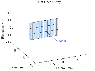
- Linear array: In a
linear array transducer, all the elements form a line. The element usually
as a rectangle shape with width in the array direction or lateral
direction, and height in elevation direction. The center to center
distance of the two adjacent elements is defined as pitch size and gap
between them is called kerf. Normally the pitch size is required to be
smaller than 1 wavelength, but some cases it can be 1.25 wavelength.
The kerf is normally around 50 microns depends on the blade
thickness to cut the elements. Linear array is widely used when acoustic
window is big enough, such as abdominal or limb vessel scan. In a linear
array, each time only a group of elements work together to transmit or
receive, i.e. the aperture size is smaller than he
transducer active surface. The ultrasound beam is
perpendicular to the transducer surface, and scan a rectangle
area.
- Phased Linear Array:
it is exactly the same as linear array in term of element arrangement.
For phased linear array, the element pitch size is required to be
smaller than half of the wavelength. In a phased array, all the elements
work together, i. e. the aperture are all the
elements, and the aperture size is the whole transducer active surface.
Phase array steer the beam by apply different delay on each element, and
it requires small acoustic window. It is widely used in cardiovascular
scan where the rib gap is the small acoustic window.
- Curved array: Curved
array is very similar to the linear array. All the elements form a line,
but it is curved and most likely is convex. Compared to the linear
array, it gives a bigger scan area when acoustic window is limited.

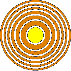
- Annular array: An
annular array consists concentric rings
elements with the center one having a round shape. Annular array
elements work together and normally have time delay to achieve focused
beam. Due to its special geometry shape, annular give best focused beam
with focal depth adjustable electronically. Most annular array have equal area elements to keep impedance of each
the same.
- Circular array: a
circular array has all the elements form a circle, facing one side.
- 1.25D 1.5D 1.75D
array: in linear array, either linear scan or phased scan, there is only
one element in elevation direction, i.e. the direction perpendicular to
the scan direction and depth. The focal depth cannot be changed in this
direction also it can be dynamically changed in lateral direction. To
improve this capability, the element is divided into several pieces in
elevation direction, with the first one, or the primary one is bigger in
size. Depends on the number of pieces and the size, it is called 1.25D. 1.5D, or 1.75D. It partially improves the elevation
focus property.
- 2D array: in 2D array,
the element forms a M X N matrix. Beam can be
steered in all the directions and thus the transducer is capable of
scanning a volume, generating echo information for a 3D image. A 64 x 64
element array will require more than 3600 channels for beamforming, and it increase
the cost of the imaging system greatly.
|
- Method:
When aperture is concave, the uniform excitation on the aperture will
generate a concave wave front, and it will converge to a point when
propagating. As shown in the following figure: The concave wave front
that is necessary to achieve the focused beam can be obtained by
mechanically shape the aperture into concave, or the using an array
transducer and control the transmit delay of each element.
Theoretically, the round concave surface gives the best focus effect.
The focal effect from of transducer can be improved with more element,
smaller element size, and high resolution delay control.
- F
number: is the ratio of focal depth over aperture equivalent diameter,
it is the diameter for round aperture, and the total aperture element
length for
array transducer. Focus effect is greatly related with
frequency, focal depth and aperture size. When focal depth and aperture
size are combined into f number, and so the focus effect will be
determined by f number and frequency.
- Focal
zone characteristics
- Beam
width: The beam width is narrowest at focal point, and it is governed
by the f number and center frequency:
- Focal
distance (length): For a focused beam, it is narrowest at focal depth,
and spread on both sides away from the focal depth.
- Maximal
Intensity: Beam also get maximal intensity at
focal point.
|
Ultrasound Beam Steering
- Mechanical:
The transducer can be swing from side to side or rotation driven by a
motor and in this way the beam can be steering like a flashlight beam
scanning an area. Because more mechanical scanning transducer is a big
single element, and most likely is a round shape, it has best beam focus
quality for fixed focal depth. However, since the transducer is in
motion, there must be an enclosure to hold the whole motor-transducer
assembly, and the whole chamber has to be filled with special liquid for
acoustic coupling. For this reason. The mechanical scan transducer will
have a shorter life time. The common failures includes the bubbles in
the chamber, swing or rotation non-uniform, and motor failure. Most
mechanical scan transducer use serve motor instead of step motor, the
transducer is in constant motion while transmitting and receiving, and
thus it is difficult for some application that requires multiple
transmits at the same locations such as Doppler imaging.
- Phase
array:
- Apodization:
- Dynamic
Aperture:
- Dynamic
focus:
|
Ultrasound Pulse Echo
Method
Ultrasound
imaging is based on pulse-echo method. The ultrasound transducer transmits an
ultrasound pulse and the switch to listen mode, recording the echo reaches
the transducer surface. The echoes from targets close to the transducer will
return firstly, and later for the echoes from further targets. Since the
ultrasound travels inside homogeneous medium at a constant velocity and along
a straight line, and thus the distance can be easily calculated. Most targets
are moving and thus the pulse has to be repeated in certain frequency to
track the target.
In human
tissue or room temperature, the sound velocity is around 1540m/s or 1.54mm/ms.
Assuming the pulse is transmitted at time 0, and at time T, the echo from
target arrives, then the distance from transducer surface to target D is
calculated:

For
example, if it takes 10ms to receive the echo, then
the distance from the target to transducer surface is about 7.7mm in water.
When
transmits an ultrasound pulse, the pulse has a time duration. If the pulse center frequency is 1MHz,
then a single cycle of the carrier wave is 1ms. The pulse transmitted
has to include at least one cycle since it is an alternative signal or
energy. At certain frequency and amplitude, the longer the time duration of
the pulse, the more energy of it, and thus it can transmit further before it
die out due to the attenuation. If the pulse is too long, the echoes from
targets that are close to each other may merged together. In this way, a
short pulse is preferred to distinguish close target. It is obvious that with
the same cycle number, higher frequency pulse will result in shorter pulse,
and can detected finer target.
- Pulse repetition
frequency, period
As
mentioned above, pulse need to be repeatedly transmitted to track targets if
it is moving. However, the next pulse can be sent out only when the echo from
the furthest target has returned. Otherwise, the echo from the far target of
the previous pulse and the echo from the near target of the recent pulse will
come the same time and true target location cannot be determined. So if the
maximal detection depth is D, and sound velocity is c, then the minimal time
interval between two pulse is :

This
time interval is also called pulse repetition period, and according f = 1/T
is called pulse repetition frequency (PRF). The higher the PRF, the lower the
maximal detection depth, and the faster the
detectable moving target.
As
soon as the ultrasound pulse energy leaves a piston transducer surface and
moves forward, it starts to spreads in all the directions, but the main
energy will confine in a disk shape when it is very close to the transducer
surface. The diameter of the disk is the same as the transducer surface and
the thickness of the disk is sound velocity multiply pulse duration. This
disk spreads as it moving forward, and eventually
will become a dome shape.
The
definition of duty factor is the pulse duration over the pulse repetition period,
or the pulse duration multiply PRF. For imaging ultrasound, energy duty
factor is very low, and thus have very less averaged power.
|
Ultrasound
Transmitter
|
- Protection
circuit, TR switch
- Impedance
control
- Gain
|
Time Gain Compensation (TGC)
- Attenuation
and beam spread
- Effect
on Image
- Method
|
Envelope Detection
- Demodulation
- Rectification
- Rejection
|
Dynamic range compression
- Dynamic
range from ultrasound signal
- Dynamic
range of display equipment
- Method
|
Ultrasound
Image Mode
- A-Mode
- B-Mode
- M-Mode
- C-Mode
- BD-Mode
|
Ultrasound
Image Frame Rate
- Image depth and PRF
- Frame rate, Number of
lines per frame, and depth
|
Preprocessing
and Postprocessing
- Preprocessing
- Postprocessing
- Freeze frame
- Black/white inversion
- Contrast variation
- Frame averaging
- Edge enhancement
|
Ultrasound
Spectrum Doppler
- Doppler effect
- Continue wave ( CW
)Doppler
- Pulsed wave ( PW
)Doppler
- Aliasing
- Range ambiguity
- Frequency and flow
speed
- Narrow band width
transducer
- receiver
- Demodulater
- Wall filter
- Demodulater
|
- Color
Flow Map
- Transmit
method
- Autocorrelation
- Flow
direction
- Average
velocity
- Velocity
variance
- Time
domain process
- Color
maps
|
Ultrasound Power (Energy)Doppler
Flow Imaging
- Method
- Application
- Advantages
and limitations
|
Ultrasound Ultrasound Image
Artifacts
- Definition
- Resolution
related
- Propagation
related
- Mirror
image
- reverberation
- Comet-tail
- Ring-down
- Side
lobe
- Attenuation
related
- Shadowing
- Enhancement
- Focal
Enhancement or Focal Bandin
- Doppler
related
- Aliasing
- Incident
Beam Angle
- Clutter
- Ghosting
or Flash
|
Acoustic Output
- Pressure
- Unit
- Peak
pressure
- hydrophone
- Power
- Intensity
- Cavitation
- Mechanical
index
- Thermal
index
|
Guidelines and Regulations
- American
Institute of Ultrasound in Medicine (AIUM) Statements
- National
Electrical Manufacturers Association (NEMA)
- Food
and Drug Administration (FDA)
|